
Intro
This topic started off as a sub section from the yet to be released article … ‘Hi-fi Hero’s: Laurence Dickie (Pt.2)’. But it’s such an important subject, I had to give it it’s own blog. If you want to check out Pt.1, you can here:

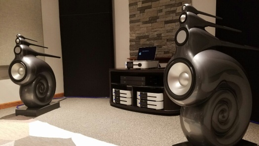
Part two will take a deep dive into the technology used on the Vivid Audio G1S speaker (below).
In this blog I’m going to take you on a little journey. If I’ve done my job, by the end I will have made a compelling argument for why a 4-way ‘pistonic’ drive unit speaker design (like the Vivid Audio G1S), is a technically better solution than a 2-way ‘non-pistonic’ design (all other things being equal).

To do this I need to work through two concepts. One is cone break-up and the second is drive unit dispersion.
Who we are
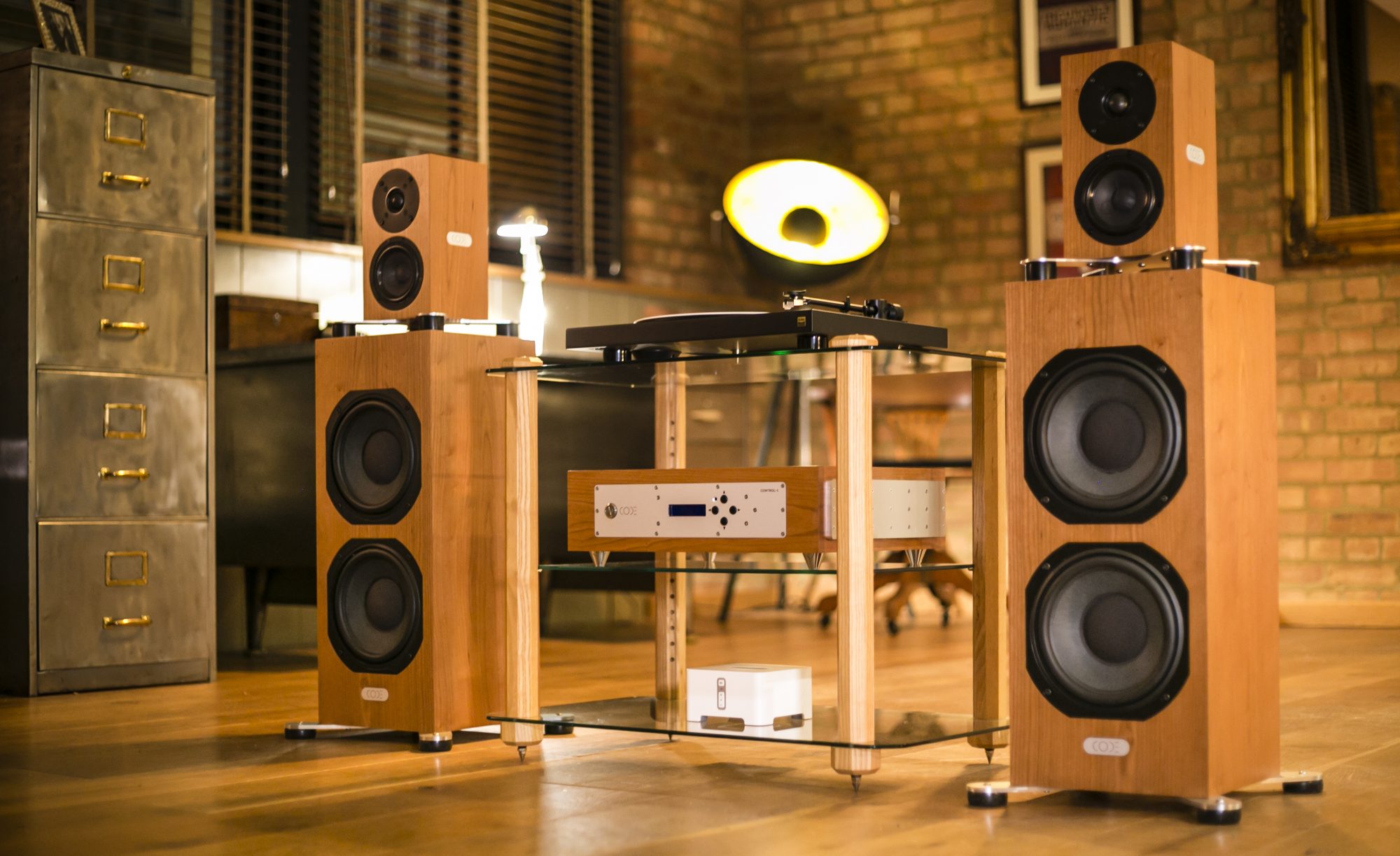
If you’ve not heard of CODE, we’re a small high end hi-fi company based in Woking, England. My name is Ceri Thomas and I’m the founder and chief designer:

We specialise in active, DSP speakers, and you can see our SYSTEM-1 speaker below:

If you’re interested, you can find out a little more about that speaker here:
Pistonic motion – the basics
A hypothetically perfect drive unit will move pistonically at all frequencies i.e. like a piston in an internal combustion engine:

What that means is as the voice coil moves forward, so should the diaphragm with zero flex i.e. it is infinitely stiff:

In video form, it’ll look like the below. This is pistonic motion:
Unfortunately real word drive unit diaphragms are not infinitely stiff and in certain conditions will not act as a piston. Instead, the cone will start to ‘break-up’. Not literally (!) but in the sense that the diaphragm will start to flex. This is non-pistonic motion:
Is it a problem?
Yes, it’s a big problem. Listening to a drive unit diaphragm in break-up is at best fatiguing, and at worst, just unpleasant. At low volume levels it’s tolerable, but as the volume is increased, the issues become ever more pronounced.
It can be particularly bad with PA speakers and I often find myself being compelled to leave a bar or stage if the system is suffering heavily from cone break-up.

Can you describe the cone break-up?
There are two main types of break up resonance; concentric and radial. Both will have areas of the cone in positive and negative phase, which will to a certain degree will self-cancel:
*the below four diagrams are taken from Martin Colloms, High Performance Speakers, 6th Ed, John Willey:

This is an example using a laser plot:

Then you have radial, or bell modes:

and again an example of this using a laser plot:

But it’s not just the cone you need to worry about. The surround also causes issues too. The laser plot below shows the surround displaying excessive amplitude, but still in phase with the cone. This will happen in the frequency region before the first concentric nodal resonance (covered above):

Slightly higher up the frequency band, but still before the first concentric nodal resonance, the surround will flip to negative phase:

These two pics were taken from the following Klippel doc:
Click to access Measurement_and_Visualization_Cone_vibration_2006.pdf
What does it look like on a frequency plot?
Below is a plot for a 6.5″ metal dome Seas unit:

I’ve highlighted the first concentric node resonance at 5kHz. The null prior to this is partially caused by the surround moving in anti-phase. You can also clearly identify the second concentric node resonance, but it’s harder to identify the radial nodes.
This whole area around 5kHz is responsible for the unpleasant sound associated with cone break-up. Really a design using this drive unit should cross over to a smaller diameter drive unit, long before the first concentric nodal resonance is hit.
Drive unit dispersion
To explain this I’m going to use an example; the Visaton AL170 mid / bass 6.5″ driver:
http://www.visaton.de/en/products/woofers/al-170-8-ohm

Here is the polar response:

What this shows is as the frequency rises, the dispersion pattern changes. At 500Hz (black) the drive unit is pistonic and the sound level is constant through the full 180 degrees.
But as the frequency increases, the dispersion pattern changes. In effect the dive unit starts to ‘beam’ as the radiation pattern becomes more focused on-axis i.e. right in front of the speaker. By the time the dive unit is at 8kHz (grey), there is very little output unless you are stood right in front of the speaker.
Why does this happen?
Well it’s related to the physical size of the diaphragm and the important formula is as below:
ka = cone circumference / wavelength
The left hand side of the graphic below shows how the dispersion reduces as the wavelength becomes small, relative to the diaphragm circumference. ka = 2 is the point where dispersion starts to narrow:

The graphic is taken from this very informative piece:
http://www.acousticfrontiers.com/speaker-off-axis-ka-and-driver-diameter/
The right hand side of the graphic shows the ka = 2 point, for different diameter diaphragms. As you can see, the smaller the circumference of the cone, the higher in frequency it can go, whilst maintaining good dispersion.
Let’s have a look at the directivity of an 8″ driver:

If you want a little proof of this, check out the three plots below. They’re all 8″ Scan Speak drivers, with the Illuminator being very expensive, the Classic a middle range driver and the Discover an affordable option. They are start to lose directivity control around 1kHz, as is illustrated above.

These plots are taken from the consistently good website below:
http://www.troelsgravesen.dk/Beaming.htm
You would normally cross a 2-way over at 3kHz. Would you fancy doing this, with an 8″ driver after seeing this? It’s already beaming prior to crossover!
It’s the equivalent of doing the below left, when to get a smooth transition at crossover, you need the below right:

A sound power plot for a 2-way (crossing for a 6.5″ mid/bass to a 1″ tweeter), with the crossover (3kHz ish) will look like this:

Taken from a very helpful BMR speaker white paper:
Click to access naim_ovator-s-600_bmr_white-paper_may2009.pdf
You can see the big drop in ‘sound power’ around the crossover point of 3kHz.
But it’s fine on axis, what’s the problem?
Well part of it is that we normally listen to music in a room, where there are multiple reflective surfaces:

The image is taken from an excellent article on the subject:
http://www.acousticfrontiers.com/early-reflections-101/
So you don’t just listen to the direct sound, you also listen to multiple reflected sounds. If the reflected sounds are significantly different in signature to the direct sound, it causes processing issues for your brain, and will damage the clarity of the stereo image.
Waveguide
I haven’t got time to cover this properly here, but if you did have to use a 2-way design, one way to match the directivities between the the mid / bass driver and the tweeter, would be to use a waveguide on the tweeter.
Funily enough, this is what Vivid Audio do with their latest KAYA range:
https://www.vividaudio.com/loud-speakers/kaya/

So what does a pistonic speaker design look like?
Well, there aren’t many. Perhaps the first and most commonly recognised one is the B&W Nautilus (below). The design was led by Laurence Dickie and was released in 1993, some 25 years ago!
As you can see it’s a 4-way design. That’s a 1″ tweeter, 2″ upper mid, 4″ lower mid and 12″ bass driver, all with lighweight aluminium cones. You can find the brochure here:
Click to access Nautilus%20Brochure.pdf
How does a pistonic design deal with cone break up?
This is fairly simple … you crossover substantially lower than the first concentric nodal resonance, so as to make this region inaudible.
Vivid Audio for instance crossover two octaves below the first concentric nodal resonance with a 4th order Linkwitz-Riley filter. Used in combination with a notch filter (on top of the resonance), the drive unit will be 48dB down at 5kHz.

If this mid/woofer were used in a conventional 2-way, with a 2nd order 3kHz crossover point, you would hear a great deal of the cone during breakup!
How does a pistonic design deal with directivity?
Well a transition between a 2″ upper mid to a 1″ tweeter (as per GIYA and Nautilus), is significantly easier than from a 6.5″ mid / bass to a 1″ tweeter.
In fact the B&W Nautilus crosses over between the 2″ and 1″ drivers at 3.5kHz, vs. 3kHz for a standard 2-way.
So in directivity terms, you are looking like something akin to the below left on the 2-way and below right for the 4-way.
As you can imagine, it’s far easier getting consistent sound power with the pistonic design.
The waterfall plot comparison

Finally here is the proof. The below two plots are lateral dispersion (waterfall) plots. The first plot is for the Vivid G1 (above) and for comparison, the second plot is a high quality 2-way design:


You can find the Stereophile G1 article here:
https://www.stereophile.com/content/vivid-audio-g1giya-loudspeaker-measurements
The comparison 2-way is the Ariel Acoustics 5T, also completed by Stereophile (below):
https://www.stereophile.com/content/aerial-acoustics-5t-loudspeaker

John Atkins (from Stereophile) describes the G1 plot:
‘The radiation pattern is admirably smooth and even between 500Hz and 8kHz, something that always correlates with stable, accurate stereo imaging.’
I couldn’t have said it better myself John!
You can see the off axis dispersion issues with the 2-way around the crossover point at 2.7kHz. In comparison the G1 is extremely tidy. The crossover points in the upper region for the G1 are 880Hz and 3.5kHz.
Conclusion
Hopefully I’ve demonstrated that consistent sound power through the crossover region, and keeping the drive unit diaphragms pistonic*, are important for high quality sound reproduction.
*Or as close as practicably possible
And in doing so have provided a compelling argument, as to why a pistonic speaker design is a better solution for accurate sound reproduction, than a non-pistonic design.
Sign off
Thanks again for reading one of our blogs!
As ever, if you have any comments or suggestions, please get in touch:
info@code-acoustics.com
Ceri Thomas
Founder & Chief Designer
CODE Acoustics
https://www.code-acoustics.com
https://www.code-acoustics.blog
https://www.facebook.com/CodeAcoustics/
